|
So I released new board revisions over the past few days, I have done my best initial check on these but I have not yet ordered them to build up. Even if I had ordered them I would still correct any mistakes in new revisions so the files might as well be public.
I am also working on a differential version of the PCM4202 ADC board, I did have a revision 1.0 design but I am not happy with it and so decided to rework this. It should be a more versatile solution than the single ended version and have a better PCB layout. I also came across Orange Pi SBCs which look very neat with the AllWinner H3 SoC onboard all of them. Early 2015 I had started designing an ADAU1452 Raspberry Pi hat type board, unfinished designs still available at github.com/pwzj/ohdsp. I stopped working on this as the Pi only support I2S in stereo with no TDM, limiting what I wanted to do with it. The AllWinner H3 SoC datasheet specifies support for all the normal I2S/left and right justified/TDM modes on the audio data lines and so this may work for my original idea. I am very tempted to either spin an ADAU1452 DSP board to interface with this, or make an adapter board to hook into my current DSP design. This all depends on software/driver support for TDM mode, and I need to do a lot more research.
0 Comments
So I finished revision 2.0 DSP board layout, I need to run some final checks over this and make sure it is ok. A tweaked power supply layout with solid ground planes is complete except for some track/polygon overlap errors; not sure why they are errors as the PCB looks fine. I got close to finishing some changes on the ADAU1966 DAC board and then ripped up the jumper/spi header/power supply sections as I am just not happy with the layout. I also thought switching to a 4 layer board would help. As I am aiming to use this as the main analogue output source for several projects the extra cost of a 4 layer board is justified to me. I also invested in a new toy: 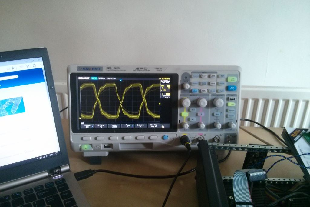 It's a Siglent SDS1202X - initially I ordered the SDS1102X but changed the order. As it is only 1GSa/s shared between 2 channels the full 200MHz bandwidth is limited when using both channels at once. As I would like to be able to probe up to 50MHz square waves the extra bandwidth is useful even if it is only really accessible with only 1 channel on.
It's a nice piece of kit, I have only played with it a couple of times so far. The features it has are unbelievable for the price, even some of the megabuck scopes I have played with have less features than this by default! I had been hoping to redeem the free decode option currently advertised on the Siglent website but heard nothing from my email yet. You do get decode free for 30 uses anyway, although I am not yet sure if things like SPI decode are any use on the 2 channel oscilloscope, unless the SPI clock can be used on the trigger input. Just a minor update. One of the issues I faced with building the boards was the lack of clear parts lists/parts types. Initially this is because I was not totally sure on what parts would be, how much they would all cost and so forth. I just designed what I wanted based on what I could get rather than making it a cost driven design.
Now the limit is because of the lack of information I have put into the schematic designs, and that the fields I need are missing from each component. Adding them is a slow/time consuming process. I am also trying to get KiCad to output a nice CSV BOM file automatically. Presently there is misalignment between the heading of a column and the contents of the column, but I am not sure why as it should work. Someone kindly pointed out the eeschema library file was missing from the git repository. I did notice a few weeks back and had committed the file. I obviously did not push the update to the master branch though!. Which brings me to board revisions 1.1/2,0. The ADC board revision 1.1 is almost ready to release with correct power pin assignments, I am also working on a newer revisions of the DSP boards with a master SPI connection. There is a new revision of the DAC board with the mating slave SPI connector. This means the ADAU1452 should control the ADAU1966 for faster sample rates without the need for a microcontroller. I am also revising the PSU and buffer board. This is mostly component spacing and silk screen tweaks. On all boards I have decided to switch to some lower cost regulators in digital supplies. The TPS7A45xx series are quite expensive but I will still use these in the analogue supplies due to their low noise across the audio band.. I have also been playing with RightMark Audio Analyser. There seems to be a problem with Intermodulation distortion+noise readings using the SPDIF input on the DSP. THD at lower frequencies is high on the SPDIF input as well. Otherwise the measurements seem to fall in the noise floor of my Xonar U7 soundcard. Some of the noise issues are from low level 50Hz and multiples (a lot actually, all the way up to 500Hz). This is a very crude test so take all results with a pinch of salt, but it is interesting anyway. Results shown below. First result is the Xonar U7 analogue output connected to the Xonar U7 line input. Second is connecting the Xonar U7 analogue output to the DSP platform ADC analogue input, and the DAC analogue output to the Xonar U7 analogue input. Third is the Xonar U7 SPDIF output connected to the DSP board directly, and the DAC analogue output to the Xonar U7 analogue input 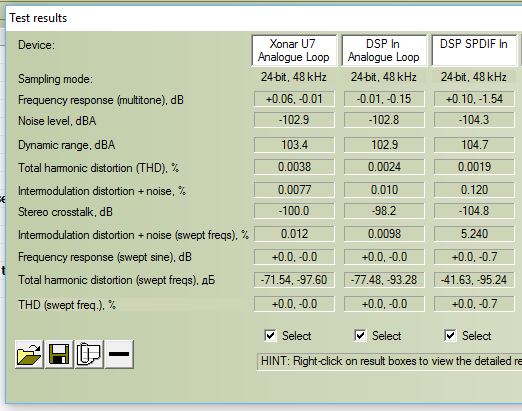 Finally soldered an EEPROM (well a socket actually) on one of the DSP boards and it self boots just fine. Here is a bad phone picture showing the DAC buffer board (single ended outputs) and the PCM4202 ADC board wired into my test chassis. Boards are stacked so the DSP and DAC are underneath. 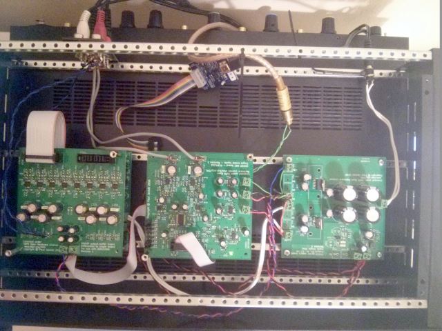 So, the reason the PCM4202 sounded so different to the digital input is because.... I have wired left to right and right to left (or LRCLK may be inverted). Also I think the phono cable I was using was faulty as well.
Having replaced the cable, swapped the channels in SigmaStudio (which is nice!), and set the levels between the two to almost the same, the analogue and digital inputs sound pretty much similar to me. If anything I would say the digital input sounds a little more clinical. I guess that is partly down to the sound card I am using to generate the analogue audio from my laptop in the first place (a Xonar U7). So after a little bodge on the power pins the PCM4202 lives. Using the ADAU1452 with sigma studio is nice, also my soundcard can toggle between SPDIF and Analogue out on the fly. This means I can compare direct digital into the DSP with the analogue sound into the PCM4202 and back out again through the ADAU1966. Whilst this seems pretty "pointless" it is quite useful if the intended use is as an active crossovers after existing audio equipment.
I didn't expect there to be such a big difference in sound, I'm not sure how much of an effect my sound card is having but this isn't anything subtle at all. Whatever is causing the difference both options sound fine and I could listen to either of them all day. . Well it would if I didn't use my lab supply and bring the rails up slowly!
The DVDD and DGND pins on the schematic are reversed, what makes it an even more annoying is that the library part is correct so no excuses really! I've "bodged" a board which powered up fine now with 2 lifted pins/wires. Just need to test it with audio tonight. Given these boards cost $25 I will junk them and order some fixed ones. In other news I am crunching through building/testing other boards (all release 1.0). Initially building two boxes. One will be a fixed analogue single ended inputs/outputs to play with as a crossover box. The other will be my experimentation box to try anything I can with. The DSP board with an ADAU1450 chip talks fine to SigmaStudio as well. Two out of the 3 LFCSP chips I hand soldered are alive, just one board left to test but that is missing some parts which I have ordered. I am also working through schematic/PCB designs to release version 1.1. of all current designs with tweaks to layouts (part spacing mostly), errors fixed, and better silkscreen labeling of jumpers/power connectors. The KiCad library will be updated when these are released as I have fixed errors in PCB footprints. I am also thinking about making this site a little more friendly if I can. Also need to finish content on the hardware page with a little info on each board (think pictures with captions and so on). So I have been digging into clocking on the ADAU1452 and the ADAU1966. I have previously played with some AKM DACs and generally if the ratios of MCLK/BCLK where correct it didn't matter what sample rate you fed the chip it would work just fine. This does not seem to be the case with the ADAU1966.
In stand alone mode I can only get the ADAU1966 to work at 48kHz, and if you look at the register settings this seems to be it's default mode. This does not seem to be explained anywhere clearly in the datasheet. I have tried running at 96kHz, with all the clocks correct, and audio comes out, along with lots of extra noises. To be honest it sounds good to me at 48kHz. which is good for running in TDM16 mode that is limited to 44.1/48kHz. If I had included a master SPI port on the DSP board then I should be able to control the DAC chip through SPI. I wasn't sure how this would work with self-booting though and was trying to keep it simple. So I hooked up my Gould oscilloscope (50MHz analogue bandwidth, not calibrated) and checked a few things out, the circuit looks fine from what I can see. The picture below could be any random square wave from anything, but it is actually the BCLK signal probed right on the DAC input pin (right on the package). It looks pretty clean. I can not work out why it seems to be running half the speed it should. It seems to be 6.144MHz, I was expecting 12.288MHz. That might explain why the DAC sounded horrid running at what I thought was 48kHz. Half that is obviously 24kHz which isn't ideal for audio! I think it is a software thing (SigmaStudio) as the hardware looks and tests just fine, or I could be calculating it incorrectly.. 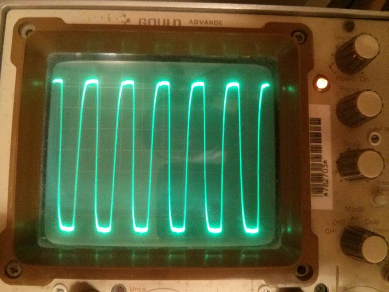 |
Paul JanickiAn electronics engineer and a long term electronics hobbyist. I like tinkering with stuff and making things. Archives
July 2022
Categories |
 RSS Feed
