|
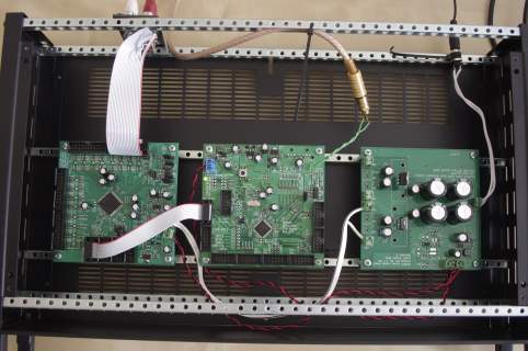
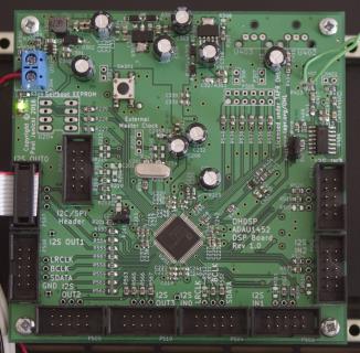
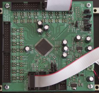
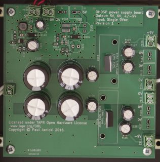
Have been playing with an initial test setup on 3 boards (DSP, DAC and PSU) screwed into a 2U rack case. The boards are the ADAU1452 board fitted with an ADAU1452 (I also have an ADAU1450 to test). The ADAU1966 DAC board. And the power supply board with only the 5V switching supply fitted. Just to note the 6V supply was added to drive things like the analogue supply on the DAC but as the current draw is so low the 9V output can be used instead.
The DAC board is currently wired to some phono sockets using only the positive output from the DAC (ignoring the negative terminal). This is through the passive filer only so there is DC present on the output. I have not yet tested everything but the ADAU1452 DSP chip on the board I am using works. I do get 1 PANIC flag set in the core control under SigmaStudio after Downloading to the DSP (changes depending on settings). If you clear the panic flag this it does not come back. I need to test another board or two to see if this is a problem with my board/soldering method or something else. However so far the DSP does work and is happy to sit on my desk all day long doing so. I do need a fast oscilloscope to check all the signals properly and adjust drive strength settings. Not sure I can borrow one at the moment so I might just have to invest in a reasonable Rigol mixed signal oscilloscope. The alternative would be a good analogue only oscilloscope and a USB logic analyser but it can be useful to have it all in one piece of kit. The ADAU1966 DAC chip works and sounds pretty good directly driving a single ended headphone amplifier with only the passive filters. I have been running the sample rate at 96kHz to the DAC. This sample rate needs to use 2 I2S ports running in TDM8 on the ADAU1452. I do have an issue where the DSP will handle a full scale SPDIF signal, but if I do not reduce this by 12dB then the DAC distorts. I did not have this issue with the first program I downloaded to the DSP so I might have changed something by accident. I have been using the asynchronous sample rate converters on the ADAU1452 to feed SPDIF from my laptop to the DSP board. If you are not careful with sample rate settings in the DSP and to the DAC you can also make it sound average to horrible (think badly compressed MP3) so you have to be careful. Just some close up pictures of the boards (click to view larger images):
0 Comments
Well it works as this bad video showing my terrible test setup on a stupidly small table shows.
I am driving SPDIF into the ADAU1452 DSP which is feeding the ADAU1966 DAC. Input sample rate is 44.1kHz, output sample rate is 96kHz. The ADAU1966 is driving a single ended headphone amplifier, through the passive filters only (no active buffer!), through thin phono cables without issue. And it sounds pretty good (very very good to my ears). The video shows a bench supply but the setup is now running on its own power supply. I shall take some higher quality photos when I get a chance. So I have almost finished building up a number of boards bow. (Pictures to follow)
I have left off PSU filtering parts (ferrite beads and 1ohm resistors) so I can test the power supplies and bring in each section of the board independently. This will be the easiest way to check for design errors/mistakes. I can also test PSU stability before potentially damaging anything downstream. Just need to power it up. Time to see if all this effort has been worthwhile! So all these boards are SMD parts except where they can not be or there is no point. I have built up many boards down to 0402 sized components and personally do not see most parts as a massive challenge (if you are careful). In fact having watched a 70+ year old engineer chew through 0603 parts on some crazy looking fragile board modifications I do not think anyone should be scared of trying out soldering on SMD parts.
If you do look at this and wonder if you can have a go at SMD parts then just give it a go is my advice. You can pick up 100 quantity of resistors/capacitors from any decent electronics supplier for next to nothing (much less than 1USD), if you have some good old fashioned strip board/vero board then you could practice soldering some SMD parts between the copper strips. Its not perfect but you will pick up how to make a good/bad joint and it really does not matter if you damage the parts in the process this way. I have so far been building up these boards with my "normal" soldering iron bit (2mm or 3mm?) as I can not find my fine tips. They are not finished and I have not powered the boards up yet but so far I have had no issues using simple methods such as wicking excess solder off parts, and even just wicking solder joints to improve the quality of them if needed. I am using leaded solder (old fashioned 60/40 Multicore Ersin solder) which is much easier to work with. Trying to reflow or correct a lead-free joint just makes it look worse most of the time (no matter how much flux you use), from my experience. Still building up boards slowly and rationalising the components. Seem to have over done the decoupling capacitors a bit, although its easier to take them out compared with having to bodge some on later.
Also (tried to) stick a link up for this site on diyAudio, have to see if the thread gets approved, Not sure if anyone will be interested though, plenty of other DSP projects on there. Started building up boards yesterday, using a rather big soldering iron bit as I cannot find my finer tips anywhere (unless I didn't actually buy any with my £35 ESD safe iron.
Finding a few mistakes on the way like pin 1 markers missing on silk screen. No idea if the boards will work, well specifically the ADAU1450/ADAU1452 boards I am building, So I ordered a lot of components (spares as well) to build up some boards, they have nearly all arrived over the past couple of days. Will look to start build up boards ASAP.
Been trying to tidy up designs a little, such as using cheaper diodes and regulators. On the diode side I keep getting that wrong. Found some cheap SS14 diodes in SOD-123 package, so ordered the SMA version instead. Before that I also thought I had ordered some SOD-123 B140 diodes, and they are SMA as well. .Have a lot of SMA diodes I don't need now... Some of the parts are moisture sensitivity level 3, meaning you have 168 hours to solder them before you have to bake them before certain types of soldering. Hoping to get these mounted at the weekend, not sure how hand soldering affects moisture sensitive parts, but I shall get it out of the way and not worry about it. |
Paul JanickiAn electronics engineer and a long term electronics hobbyist. I like tinkering with stuff and making things. Archives
July 2022
Categories |


 RSS Feed
