|
So not to be negative but...
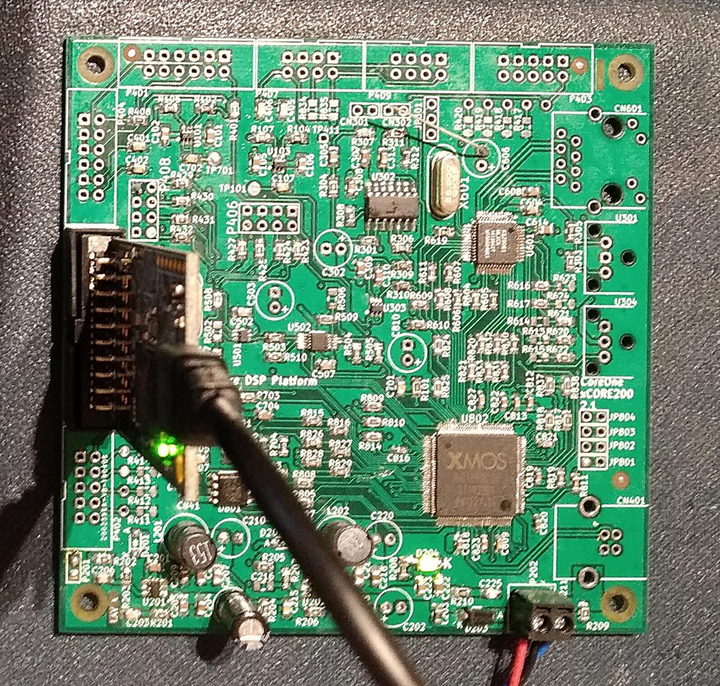
I found my XMOS board, and went to install the XMOS dev tools... Nope not what they were. Now just a complier (that not longer supports their special code), and no GUI provided. Talk about a let down, and a MASSIVE retrograde step. Not sure I can be bothered. The NXP i.MX rt600 processors look pretty awesome...Happy to ditch the XMOS hardware and move to something better... So lets start doing some development, using my Bitbucket account with Sourcetree as usual.... Nope, we now only support app passwords. Okay...Lets set up SSH keys....nope doesn't work....okay lets setup an app password and use it... "remote: Bitbucket Cloud recently stopped supporting account passwords for Git authentication." I AM NOT USING MY ACCOUNT PASSWORD!!!!!!!!!!! WHY do companies make using my own account impossible. I do not mind 2FA and so on, but to not be able to log in at the most basic level., just not on. My DSP box is disconnected following a "degradation in performance". I think I massively overloaded the ADC too many times without protection;. Although it still works fine if plugged in and not turned up too loud, so it's pretty robust even if you try to blow it up. (Call it an endurance test). The passive crossovers I have sound pretty good (not as good), but fine for pretty much everything I need at the moment. The only limitation - my amps get too hot. Benefit for DSP with 8 channels vs passive with 4 channels, DSP setup runs cooler, and can play lounder for longer. I do want to build some new boards, but a career change has left me with less money, so even though I now have the time to do it, I can't afford it....Hoping that will change soon, but I am not counting my chickens... On the plus side this new career seems, different, I hope in a good way, but we will see.
0 Comments
Well I just googled "waffle" and the first results were not expected, think there was a technical issue...
Still rocking my DSP box on my speakers. Still sounding very good. I am sure it could be better though. Time to warm up the snake oil!
Lots of thoughts on this project, such as how could I sell something people might want to buy. Likely not for profit (just to cover my expenses from doing it), at least at first until I can create a range of boards with ultra low jitter clocks and coax cable interconnects for all the signals, then we will be into the realm of proper hi-fi.... Some ideas I have going forward for now: Just fit another flash chip to the XMOS board. I STILL cannot get the stupid thing to work with the current flash chip. I think changing to another device is possibly the easier option, unless that doesn't work as well. I did get some more though. Or just build a board with the XEF device on, as that has the flash built in. I/O boards. At the moment all the designs are for the signal processing side, there is no easy option for terminating to Phono/RCA sockets or XLR/balanced jacks. With the smaller uDSP and uCodec boards would be easy to make a motherboard for these with connectors on. But it would limit the flexibility of the system going that route. Still thinking on the digital video option, would be nice if there was an easy way to get digital audio in from a royalty free interface like DisplayPort and use this to create a preamp/processor solution. More of a dream still, but there must be a way... On a side note had a job interview with a very interesting company recently. Good to see a company that not only makes interesting products, but wants to deliver the best they can and keep improving as technology gets better. Still enjoying my active setup, when it is plugged in.
Had electrical work done so felt like I have moved house several times and not gone anywhere. What I have learned is that an active 4 way speaker is more complex to plug back in than a passive setup... My conclusion is that active is still better than passive. Even just at a basic level, if you crank it right up, the amps hardly get warm. The AK4458 has more noise on the output, but I am still using the ADAU1966 filter board. I have mostly forgotten what I was going to do next, it's all in a box somewhere around here... Oh that's right, the XMOS board wouldn't see the flash chip. You can change the port used for the data lines, and on any port the data pins 1 and 2 didn't seem to work (0 and 3 did). Not really sure on that, unless I damaged the chip when soldering. Unlikely to kill 5 sets of output pins though! Looking online other people have had issues getting flash chips to work. I did have some alternatives to try. Which must also be in a box somewhere........ I don't normally "blow my own trumpet"..... But this is the most incredible, loudest, and just everything under the sun awesome thing every I have heard.
I have been in the SRE listening room at B&W when they were based at Steyning, listening to some of the most incredible speakers on the planet, in the room they were designed and tuned in. And I have every respect under the sun for the incredible sounding products they produced. However, me, a single person (not quite so amazing in lockdown), spent many years building some modified ZDT 3.5 speakers (or that should be "ZDT 3.5" speakers). They are close but the cabinets are different. I have built both the original passive crossovers (tuned by my own tone deaf ears), and also my custom designed and built 192Khz/24bit digital crossovers. These speakers are awesome with the passive crossovers. But I DARE anyone to try connecting them, through custom crossover hardware, through 8 channels of decent amplifiers you can find (original or fully refurbished commercial amps like my ones), and then compare to the 2 channel passive setup. I am no true audiophile. I could not care less if you use the cheapest aluminum electrolytic capacitors everywhere, or use polyester capacitors instead. I will not hear the difference (and if you can, "hear a difference", maybe you should just go outside for a while and get some fresh air...). But the difference between a passive 2 channel active setup, and switching to fully active 8 channel amplification, there is no contest. 8 channels of amplification, dedicated to the required frequency range of each driver, you will NOT match this with a passive setup. I have a pair of Bowers & Wilkins CM10s here, in fact, whilst they have the "wrong" bass drivers (the spiders on the bass drivers are tighter than the actual commercial versions), they are an amazing pair of speakers, But the fact I can put a pair of homebuilt 3.5 way speakers. with 8 channels of commercial amplification, and they sound as good, or better in many cases, just shows what you can do for the the same price if you put a little effort in yourself. So the noise is the attenuator box I built. I mean it is sat right next to the TV.
Well that was a simple fix! (Removing it that is). Well this thing does sound damned good, but I hadn't done my "can I hear it" test...
How close can you get to the speaker before you hear anything. Well on the mid-range there is a bit of noise up close (1/2 meter or closer). Only when my plasma TV is on though. Interestingly it's exactly the same noise my you can hear the TV making anyway. The output buffer board is the one I designed for the ADAU1966. The AK4468 recommends different filters, and much faster op-amps. The ADAU1966 app note has 10MHz parts, I am using 8MHz. The AK4468 recommends 80MHz parts from Texas Instruments! So I may just design a new buffer board. I should have done it anyway. There are no words or pictures to describe this.
So the PCM4202 and AK4468 are running at 192kHz/24bits. This gives me goosebumps. I am happy. So I pulled out my crossover box.
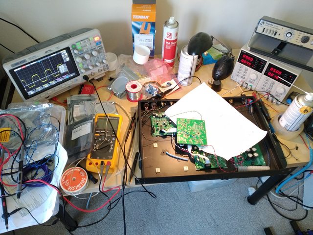
I also built up an AK4458 DAC board with an AK4468 fitted to add some VELVET SOUND (they are pin compatible). This is now fitted, but not quite working yet! Need to get all the clock rates right, but it should run at 96kHz and possibly 192kHz all in hardware (pin control) mode. Unlike the ADAU1966 which was stuck at 44.1/48kHz in hardware control. I have tuned up the termination resistors a little. Output pins from the ADAU1452 look fine at 75Ohms over the ribbon cables. The NB3L553 clock fan out seem better with 47Ohms. However the signal at the output end is not perfect as you can see some reflections interacting with the signal. That seems to be feeding visible jitter onto the clocks. At the receiver end, where the signal "slopes off" a little at the top as in the picture above, you can see the signal moving around on the oscilloscope. It's different for each board so the PCM4202 looks different compared with the AK4468. So it's all down to compromise (unless you want to tune everything perfectly, which I might do sometime...) It's giving me some more ideas for other designs. Would be interested to play with some designs with U.FL connectors/cables instead of ribbon cables. Try and reduce any interaction between signals. Plus U.FL has a small footprint so might work quite well. Also look at adding some better driver ICs in (or better clock fan outs). I did have some nice ones I had found that are designed to reduce jitter. Have used them before and they are very very good. Although it will all add complexity and cost, and I really doubt I would hear a difference, and they are a PITA strange PCB footprint... Standard power up tests:
Any loud noises on power up? Nope. Any smoke? Nope. Then we are GOLDEN. xTIMEcomposer studio see's something, but also throws up errors about connecting to xmos.com every time I try to do something useful. There is always something that just gets in the damned way of something just working! |
Paul JanickiAn electronics engineer and a long term electronics hobbyist. I like tinkering with stuff and making things. Archives
July 2022
Categories |


 RSS Feed
