|
The DSP board in the crossover box won't program or boot from the EEPROM. Even though it did work fine before, and the DSP seems fine when programmed directly. Had my scope on it and everything, the chip select line seems to do it's thing but no serial clock or data activity. Electronics drives me crazy sometimes. Probably some setting i've missed in SigmaStudio....
Mini rant over....
0 Comments
A new module is up on GitHub. This times it's a dual stereo headphone amplifier, although it is 4 indepentant channels connected to 2 stereo jacks so you could do what you want with it really.
Design is a little over-complex. It has balanced to single ended buffers feeding two good old fashioned dual potentiometers. There is then an op-amp based class B amplifier for each channel. Gain is set at 0dB for initial testing as the ADAU1966 puts out good voltage, but gain could be increased where this is needed. I have used these type of headphone amplifiers before and they seem quite stable and they will burn out the headphones before you run out of volume/power... They can also drive small speakers if needed. Design untest at the moment, and the 220pF capacitors on the op-amp negative inputs may be not-fitted or a different value in the end. Well the ADC in box from the previous post now has a dead I2S port - having set the ADC as master and the DSP I2S as master, seems like the DSP chip won the battle of which output can blow up the other output and survive.
Oh well, nothing like product testing to the extreme (intentional or not) to show up any gremlins or bugs. So for a year or so I had the new PCM4202 ADC board knocking around without all the components on, well I finally finished it! Several weeks ago in fact.
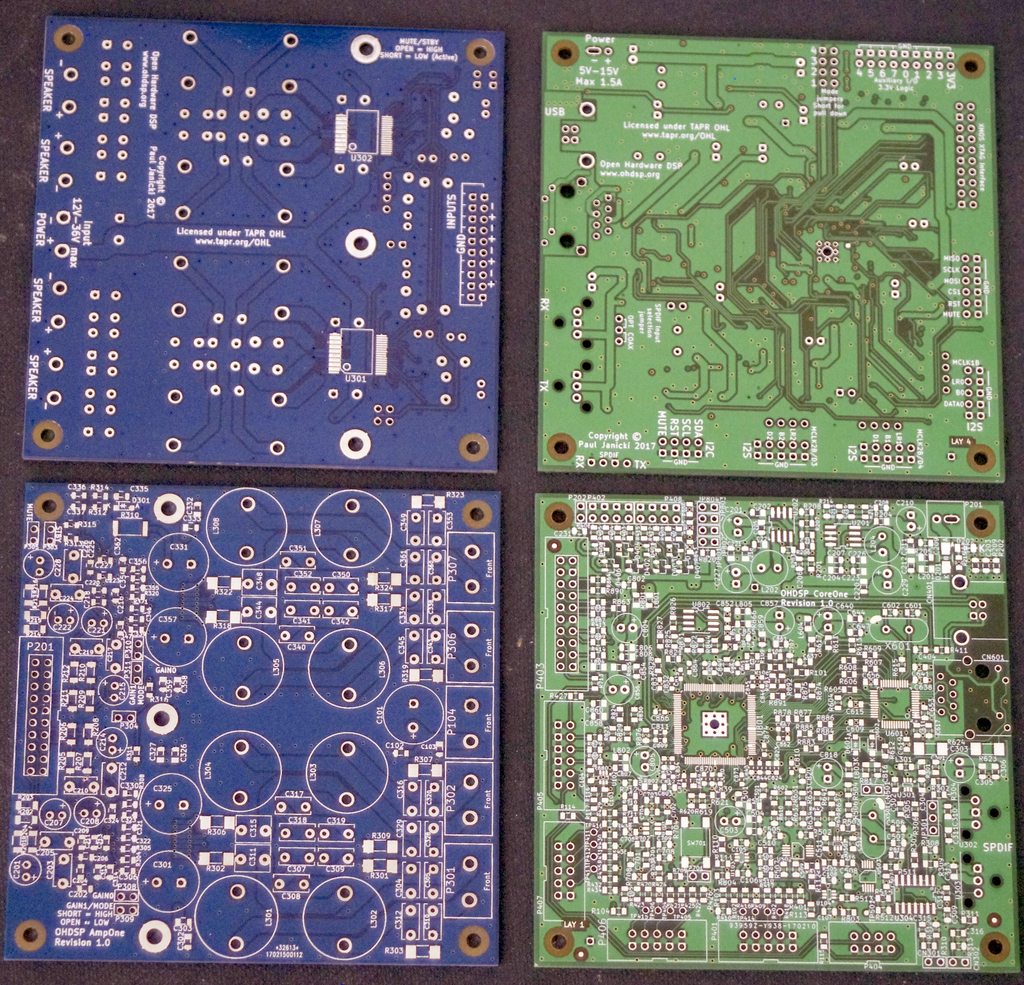
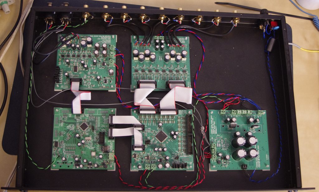
It's now built into my crossover test box. Photo of incomplete unit is in a previous blog post and the photo of the built unit is below! So new PCBs arrived this morning, fresh from DirtyPCBs. Obviously they need building and testing before I can say they are awesome (I'll remove the battery from the smoke alarm before turning them on):  The two designs are the CoreOne and AmpOne. I have some parts, need to order other parts from Mouser. So I shall get right on that. CoreOne is cramped, having tried to do single sided SMD parts only; this would be better for manufacturing as it would reduce cost and allow wave/jet soldering of the through hole parts. If I ever get any significant quantity manufactured, assuming they will work... My priority is getting the XMOS chip up and alive and talking with the XMOS development tools, then I would like to try some of their examples for Ethernet and USB. This could get interesting.... So, next up is a headphone amplifier (AmpTwo) and a bluetooth interface (BlueOne - if you couldn't guess).
Headphone amplifier is pretty basic, I can get dual stereo out of one of the audio connectors of the ADAU1966 DAC, might as well make the headphone amp a dual stereo design. Component placement is 90% there, need to route the PCB, so I am sure the component placement will shortly end up as 100% incomplete again! The next thing I would like to play with is aptX bluetooth. Now the only module I can currently find that is easy to use, and I have used before, is the Blue Creations BC127-aptX module. However these are not cheap to buy, stupidly expensive in fact. I will see if I can spin up a small (maybe 5x5) PCB to hold one of these as it would be nice to play with some wireless audio. And if it's not viable/too expensive, I can always design something else in the future. |
Paul JanickiAn electronics engineer and a long term electronics hobbyist. I like tinkering with stuff and making things. Archives
July 2022
Categories |

 RSS Feed
