|
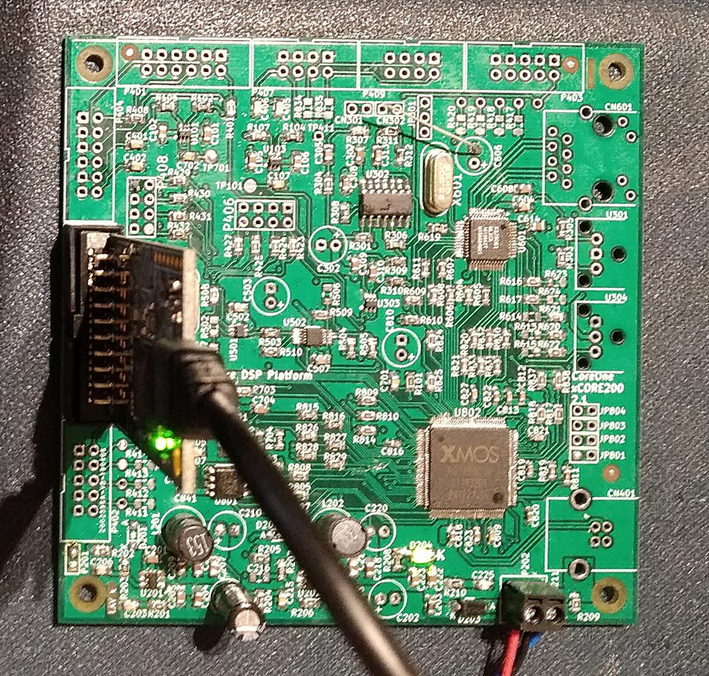
Standard power up tests:
Any loud noises on power up? Nope. Any smoke? Nope. Then we are GOLDEN. xTIMEcomposer studio see's something, but also throws up errors about connecting to xmos.com every time I try to do something useful. There is always something that just gets in the damned way of something just working!
0 Comments
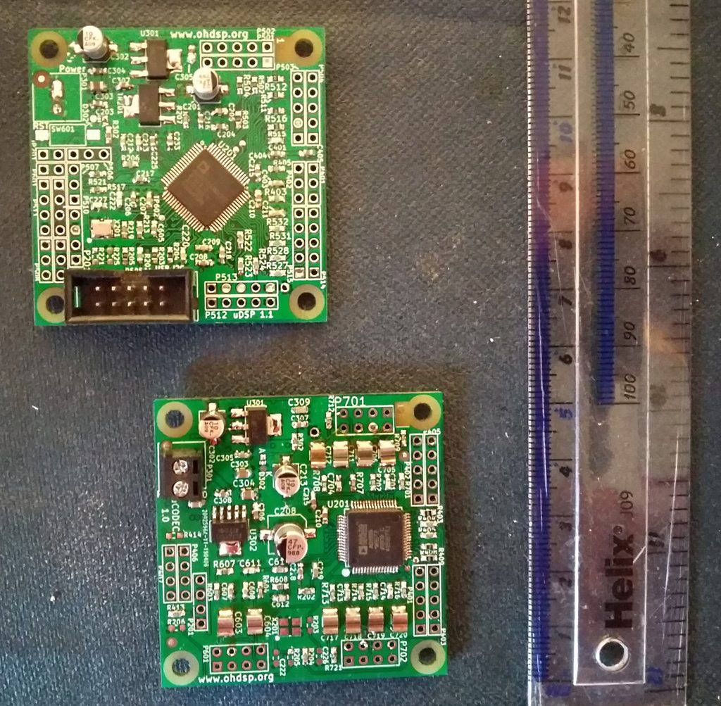
uDSP and uCODEC above.
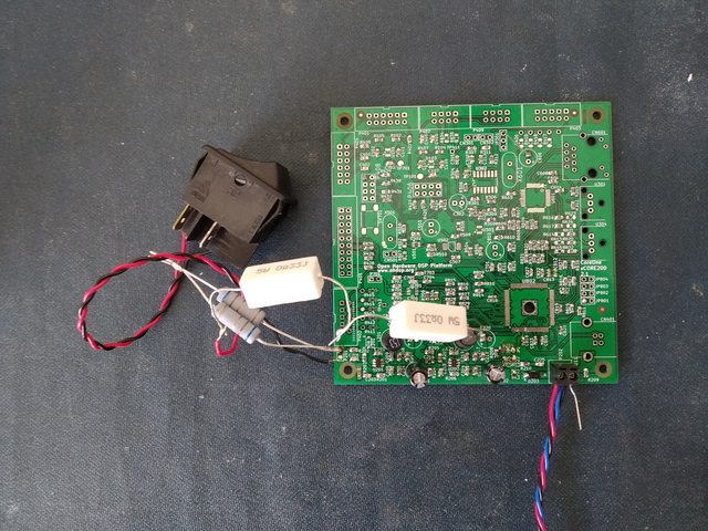
Both power up without smoke. uDSP talks to SigmaStudio, I have fitted an ADAU1450, but the crossover program for my ADAU1452 loaded onto it (I assume the unused registers are just ignored), it was putting out the expected clocks. It's missing the EEPROM - ordered from both Digikey and Farnell and forgot to get a SOIC-8 EEPROM. Need to test uCODEC with clocks. But I need to get some tall 2.54mm headers, then I can stack them as intended. Some people use programmable electronic loads, I use a resistor and a burnt out mains switch. Well it does the job.
That's my new CoreOne-xCORE200 board, only had it for over a year waiting to build. Less cramped and components on both sides, easier to build, and has the thermal reliefs I need on the ground plane. So far I am just testing the PSU to death (literally). Blew up the first two RT7285C switch mode regulators. Had the bootstrap diodes on, and then turned the voltage up too high. Ooops! Diodes of death,... Even starts up at 4.5V without them fitted, at least at room temperature, any load. Would recommend leaving them off unless you know better or you may fry the whole board. The Failure mode is to short input to output, dumping full input supply onto your 1V supply rail, the diodes survived though!. Luckily I only put 15V on it. All the ceramic capacitors are rated 16V or higher. The diodes were removed, RT7285C replaced. The power LED blew up as well, removing lifted a pad off the PCB, did the same just soldering a component on a uCODEC board. Not impressed with the JLC PCB 4 layer quality compared with DirtyPCB, but they are cheaper, 2 layer seems fine. JLC missed a routed slot off one set of boards, except the same foot print is on several boards and the others are fine. Nothing wrong in the data I sent either from what I can see. Might do 4 layer from DirtyPCB and 2 layer from JLC if the cost is okay with shipping the next time I order anything. One other issue, the RT7285C is really not stable with low impedance aluminium Electrolytic capacitors. Even with just one on the output the start up behaviour is horrible and not monotonic as the XMOS chip needs. So they will all be not fitted on this board - oh no, think of the reduction in audio quality on my digital signals... With just ceramic capacitors the performance is remarkably good. Startup behaviour is clean. The 1V rail "glitches" around 50mV max with a 0A to 1.5A load switched on, before settling within 10 to 20mV of it's no load voltage, 3.3V with 1A load is similar. Very impressed with performance, but concerned over the failure mode of input to output. Maybe need to add some polyfuses, and TVS diodes, or some post linear regulators to be safe on the next version. But you don't know this stuff until you know. Best way to find out is to put your money where your mouth is, or into the burnt out components that need replacing. Can't beat real world testing. |
Paul JanickiAn electronics engineer and a long term electronics hobbyist. I like tinkering with stuff and making things. Archives
July 2022
Categories |


 RSS Feed
