|
Or it is supposed to be here in the UK. Maybe it's taking a holiday this year.
I am now moving again, so time to pack everything up. I had been looking at my DAC boards and trying to work out why the common mode voltage seems wrong. Or more specifically why it seems to be close to the tempreature sensor reference (TS_REF) voltage. The pins are labelled as per the datasheet, and the TS_REF output is at 0V which is also not normal with default registers. I may get a little more time to play before I need to pack this stuff away, but ideally I need to build up a new board with just the DAC chip in place and work from here.
1 Comment
Belated Happy New Year to any one reading this before January runs out.
I have not done much - if anything - on this since November. I had also forgotten where I was. So I have an updated DACOne design - this is using the 16 channel ADAU1966 or ADAU1966A. I still need to track down the issue with the CM voltage on the current design being lower than expected. I have a new DACTwo design almost ready. Given the ADAU1966(A) parts are now hard to find or expensive, this new design is an 8 channel design using the AKM AK4458 device. I am still working on the CoreOne XMOS design. I had a new layout, but the track work wasn't good. The USB and Ethernet are the big issues. I would like to keep them on the same edge for mounting in a case, but the device pin out puts these on opposite sides of the IC. Other track work was long with the connector placement and PSU layout I had used so I am redoing this again. There are other issues I am seeing as well now with component supplies, both in my hobby and professional design work. Generally electronics components lead times are long now. Lead times for some simple passive parts can be 3 to 6 months or longer in some cases. It has been having an affect when trying to design for my hobby projects, or even volume quantities. You may choose a suitable, fairly generic part with appropriate size, cost and foot print only to find, by the time you wish to build it, that every supplier has low or no stock and you have to wait 3 to 6 months or change the design. I have limited development and play time for this project at the moment, and for the foreseeable future. However it will continue. I have another project that I have been working on for nearly a year now. I need to get finished in the next few weeks as it is not for me. Once done that will free up some time and space, So the current ADAU1966 boards I am playing with have a new issue I have discovered. The ADAU1966 generates it's own "common mode" voltage reference to bias all the outputs to 2.25V. Two of the DAC boards I have tested at 1.47V on the CM pins.
Something is wrong here, it may be the extra capacitance I have on the pin. The data sheet recommends 10uF and 100nF. I have 100nf, 22uF (ceramic) and 220uF aluminium electrolytic. More is always better!!! Or not, in fact that is complete rubbish. I shall remove the 220uF and see what happens. Extra PCB footprints are not an issue. It's all there to experiment with. If the changes are needed they are not really unexpected as with any project in development. In any case, and I think I pointed this out in a previous post, the ADAU1966 seems to be hard to get now. The newer ADAU1966A is twice the price and just as hard to find in stock. Even so it is still a good DAC. I am working on a revised PCB layout, it would be good to make sure all designs (new and old) and up to their best performance and working 100% 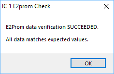 So after much head scratching the EEPROM selfboot is working again. The SPI address doesn't seem to matter as long as the EEPROM settings are correct. MP0, MP1, MP2, MP3 pins also need setting correctly - although I have changed these a few times before they are correct as it's not completely obvious.
This all needs documenting properly. Hopefully with this box of tricks now working, almost as expected pending a reduction in analogue output levels, I can start doing that. Other reworked PCB layouts are still work in progress, a few more tweaks needed to finish them off. CoreOne revision 2 is getting there. Component placement is 99% there, just need to move 4 jumpers to remove a break in a ground connection. Other PCB revisions are almost complete as well.
I still cannot get the EEPROM working on existing DSP boards. I am at a complete loss here. They used to work on early SigmaStudio versions. I shall keep poking away at it and there is a small hardware change I can try, removing a pull-up resistor on the EEPROM chip select line. I am not sure why it would make a difference now, but might be worth a try. So my 2 input (XLR) 8 output (phono/RCA) box had been giving me some worries over the past couple of months, and in fact I gave up on it for a few weeks, But I plugged it all back in last night and... it just works. Stupidity was the main cause for issue. My output phono sockets on the back actually are ordered as "4 5 6 7 0 1 2 3" to match up with the Sigma Studio output channels. As the ribbon connectors on the buffer PCB and DAC PCB are aligned in the same orientation to the edges of the PCB, when they are put together they are "opposite" and the ribbon cable has to twist 180 degrees to fit. Pretty dumb not to notice it but there we are, humanities flaws being shown in their finest hour. Simple waveform generator (ancient noisy thing) on the Right channel XLR input, mapped to channel 1 output. And it works (and it works with any other channel combo as well). Nothing special but it's a start, adding crossovers in is just done in the DSP now. Although it won't boot from the EEPROM at the moment, assume I actually put an EEPROM chip in the socket.... maybe I should go check that.... Oh and my maximum output from the buffer board with the dac at 0dB output is 5Vpp, so I need to change a few resistors on the buffer board or some amps will get fried. 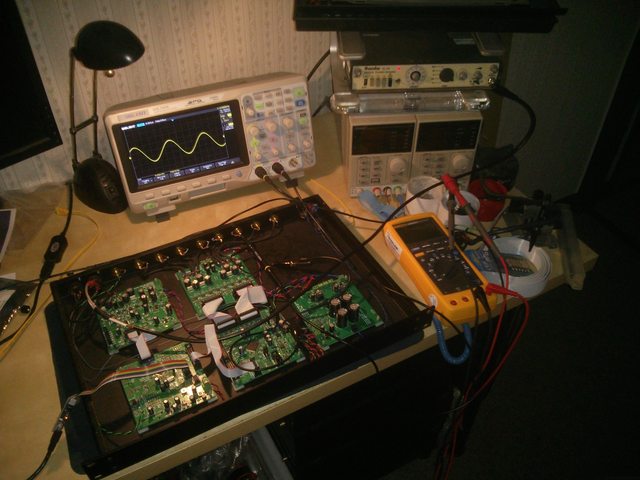 The DAC chip I have been using, the ADAU1966, no longer seems to be stocked in Farnell. There is also a new variant the ADAU1966A which looks compatible, and there is some limited stock at Digikey/Mouser. RS have stock of the ADAU1966 but the price is much higher (over double) than I last paid for a few. Both parts are shown as production parts so unsure what has changed.
Cirrus Logic offer a range of 8 Channel DACs that support TDM data modes. They have less channels than the ADAU1966, but may be usable. I need to check master clock requirements and other details but will need a new design. They also seem to be in stock at a number of places. Reworking PCB redesigns and unraveling all the interwoven tracking and component placement without destroying the whole design is hard. Sometimes it is just easier to start again!
As I have been reviewing all the designs I have slowly been making lots of small changes, and lots of small changes leads to lots of PCB rework. This is fine but I am becoming more and more busy with life these days so it will take some time. And in fact just starting from scratch on several PCB layouts may be quicker than trying to work out what I did last time. Also now looking at ADC options. The TI PCM4202 is a nice spec ADC chip but seems to have fragile I/O pins. One wrong setting or connection on the I2S interface can cause permanent damage. It would be good to have something a little more robust in it's place. Again this would be another new PCB layout, or several if other revisions are needed to fix any issues. We will get there eventually! Still working on design updates. Looking to use common parts across all designs. Also looking at making CoreOne simpler and easier to hand build. I had made it all single sided SMD components. This was mainly an experiment to see how tight it could be without making it impossible to hand build. It is rather cramped but it can be built by hand. However I will move a number of parts to the bottom side, especially optional components which are not fitted by default. It will make life easier! Also I am removing a few options that are not really needed for now.
So I am starting to work through all designs again. Specifically looking to rationalize the power supply regulators and reset circuits across all boards. And also to look for cheaper parts where possible.
The ADAU1966 DAC PCB may have an issues with the reset circuit. I used a 2.5V reset circuit (as the 2.5V rail is critical) which feeds the 2.5V output to the ADAU1966 reset pin. On several boards I have this works fine. The "trip" point should be 2.3V so some margin. However I have one ADAU1966 that is being a little fussy. Some hindsight would have been good as a couple of transistors would have pulled the reset pin up to 3.3V. However now would seem like a good time to look for some cheaper/more universal reset supervisors (with open-drain outputs). |
Paul JanickiAn electronics engineer and a long term electronics hobbyist. I like tinkering with stuff and making things. Archives
July 2022
Categories |
 RSS Feed
