|
So I could not get any version of SigmaStudio to write to the EEPROM properly on Windows 10. Then it stopped communicating completely. I ran out of ideas at this point until I I thought about using Windows 7.
Luckily I have an old PC knocking around I was going to get rid of or re-purpose. Having found my spare copy of Windows 7 I installed this as a 32 bit version - although by accident having noticed I put the wrong CD in too late! Anyway, SigmaStudio 3.14/3.14.1 beta don't seem to work properly for the EEPROM writing but communicate fine with the DSP. However SigmaStudio 3.12 seems to work just fine; I can write to the DSP and write to the EEPROM. When I selected self boot from EEPROM on the PCB jumper it starts up just fine. Just have to remeber to have the jumper on the PCB shorted and "reset"/power cycle the DSP before writing to the EEPROM with I2C/SPI. You should also power up the DSP with the I2C/SPI USB adapter unplugged; and plug it in once powered. Also must remeber to set SigmaStudio to the correct EEPROM size. I am also not seeing any random errors in the PANIC CODE section anymore which is good as I figured that all the DSP boards are unlikely to have issues. So in short; Get Windows 7 (cheap keys on ebay?); install SigmaStudio 3.12; power up DSP board in the right mode; set up EEPROM size correctly and win! Awesome!
0 Comments
So the first CoreOne PCB was going well initially; PSU section worked fine, reset circuit fine with a minor modification, clock generator was alive.
And then the first XEF216-512-C20 chip I fitted went out of alignment when soldering the large pad - and it took a lot of heat to get it back off. The second chip went on fine - apart from a couple of stubborn solder bridges. This is partly because the pads extend to far back under the device - which I can fix with a layout change. However after some checks and a power up something was very wrong! I tracked it down to 1V0 being connected to 3V3 through approx 0.9Ohms resistance - this would increase if you heated the XMOS chip up. No obvious solder bridges (which would give 0 ohms in any case). So seems chip number 2 was dead from the start; not sure why, if it was my soldering. I tried to be reasonably gentle - I can not see a soldering spec in the datasheet. Trying to remove this from the PCB resulted in damaged to the board writing it off. The XE216-512 and XEF216-512 variants are expensive, and I can not find stock of the XE216-256 or XEF216-256 chips which are half the price. Farnell says mid June for these. In the mean time I may respin CoreOne with the pads adjusted and the reset circuit fixed. I may also spin a CoreTwo with less I2S and only 1 clock gen just to make life easier. I don't mind wasting a little money; but I don't want to keep burning through £15 ICs without getting anything out of them. Oh well, onwards and upwards! So even my test box that was in my wardrobe doesn't work for EEPROM programming. In fact the latest SigmaStudio gives an error message the instant you click "Write Latest Compilation through DSP". Must be a setting I am missing on the ADAU145x Register Controls, but no idea what. If anyone has looked closely at the boards I have designed so far, and the different versions of something like the ADUA1966 DAC, you will have noted some changes to the I2C or SPI connectors. Or more specifically the fact that the ADAU1966 board has I2C on Rev 1 and SPI on Rev 2! This is deliberate; because I am still not sure what I really want as I have not used these yet. CoreOne has some better pin outs for I2C and SPI and I will look to standardize these across the other PCBs where needed. Trying to use a common I2C bus across everything would look "neat" in the first instance; but when you consider the capacitance limits on the lines it can turn into a headache quite quickly. Speaking of CoreOne, it's no where near finished yet but I am working on it: 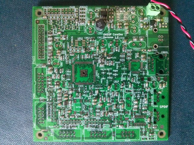 I have done very little on the project over the past week, hence the salvation as I have been unable to brake anything else! My old test box is still in the wardrobe but I am building up my first CoreOne PCB. Only resistors and capacitors so far so nothing to major, unless all the values are wrong...
This week I am hoping to try and get to the bottom of these stupid EEPROMs that magically won't work program/boot ADAU145x chips anymore. Having played endlessly with pin congfurations on several of my DSP PCBs (both previously working fine) and 4 different versions of SigmaStudio, I have managed to get the SPI_MOSI to do it's thing with data to the EEPROM, but it still doesn't work properly.
No idea. Answers on a postcard please.... I shall dig out my original test rig that is in my wardrobe and if that doesn't work; having not been used for a year since it worked flawlessly; then I give up! So having killed (possibly killed) a PCM4202 I2S interface, and finding the DSP board in the setup won't write to the EEPROM I decided to test another DSP board.
This one is fitted with an ADAU1450. It can not read/write to an EEPROM on SigmaStudio 3.12 or 3.14.1 beta. I haven't tried any other versions. I can not remeber what version I last used that worked. I have also formatted and clean installed both of my computers since then. I am suspecting a register setting is wrong somewhere... The DSP board in the crossover box won't program or boot from the EEPROM. Even though it did work fine before, and the DSP seems fine when programmed directly. Had my scope on it and everything, the chip select line seems to do it's thing but no serial clock or data activity. Electronics drives me crazy sometimes. Probably some setting i've missed in SigmaStudio....
Mini rant over.... A new module is up on GitHub. This times it's a dual stereo headphone amplifier, although it is 4 indepentant channels connected to 2 stereo jacks so you could do what you want with it really.
Design is a little over-complex. It has balanced to single ended buffers feeding two good old fashioned dual potentiometers. There is then an op-amp based class B amplifier for each channel. Gain is set at 0dB for initial testing as the ADAU1966 puts out good voltage, but gain could be increased where this is needed. I have used these type of headphone amplifiers before and they seem quite stable and they will burn out the headphones before you run out of volume/power... They can also drive small speakers if needed. Design untest at the moment, and the 220pF capacitors on the op-amp negative inputs may be not-fitted or a different value in the end. Well the ADC in box from the previous post now has a dead I2S port - having set the ADC as master and the DSP I2S as master, seems like the DSP chip won the battle of which output can blow up the other output and survive.
Oh well, nothing like product testing to the extreme (intentional or not) to show up any gremlins or bugs. So for a year or so I had the new PCM4202 ADC board knocking around without all the components on, well I finally finished it! Several weeks ago in fact. It's now built into my crossover test box. Photo of incomplete unit is in a previous blog post and the photo of the built unit is below! 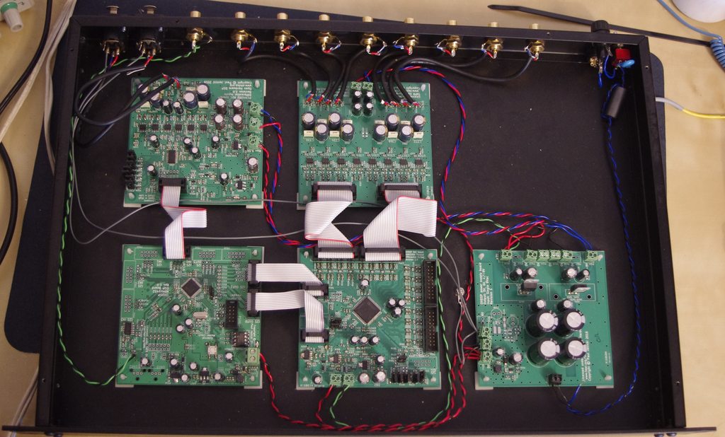 |
Paul JanickiAn electronics engineer and a long term electronics hobbyist. I like tinkering with stuff and making things. Archives
July 2022
Categories |
 RSS Feed
