|
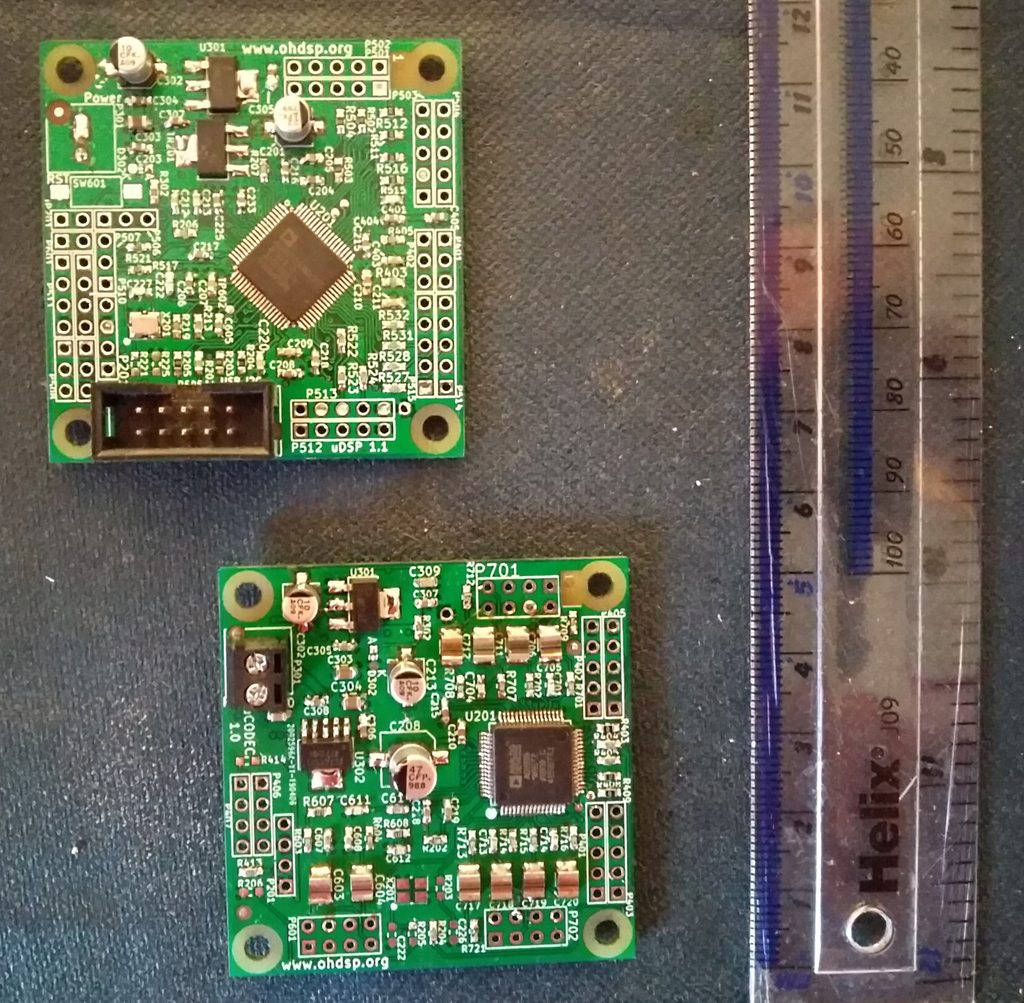
uDSP and uCODEC above.
Both power up without smoke. uDSP talks to SigmaStudio, I have fitted an ADAU1450, but the crossover program for my ADAU1452 loaded onto it (I assume the unused registers are just ignored), it was putting out the expected clocks. It's missing the EEPROM - ordered from both Digikey and Farnell and forgot to get a SOIC-8 EEPROM. Need to test uCODEC with clocks. But I need to get some tall 2.54mm headers, then I can stack them as intended.
0 Comments
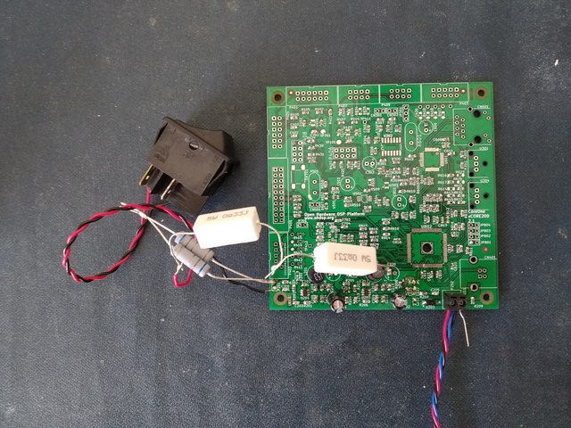
Some people use programmable electronic loads, I use a resistor and a burnt out mains switch. Well it does the job.
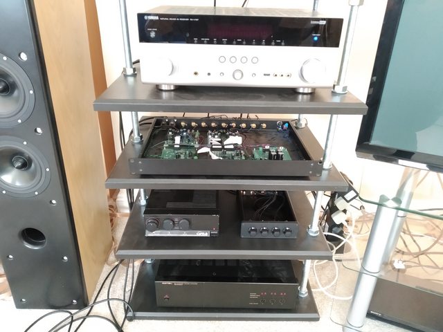
That's my new CoreOne-xCORE200 board, only had it for over a year waiting to build. Less cramped and components on both sides, easier to build, and has the thermal reliefs I need on the ground plane. So far I am just testing the PSU to death (literally). Blew up the first two RT7285C switch mode regulators. Had the bootstrap diodes on, and then turned the voltage up too high. Ooops! Diodes of death,... Even starts up at 4.5V without them fitted, at least at room temperature, any load. Would recommend leaving them off unless you know better or you may fry the whole board. The Failure mode is to short input to output, dumping full input supply onto your 1V supply rail, the diodes survived though!. Luckily I only put 15V on it. All the ceramic capacitors are rated 16V or higher. The diodes were removed, RT7285C replaced. The power LED blew up as well, removing lifted a pad off the PCB, did the same just soldering a component on a uCODEC board. Not impressed with the JLC PCB 4 layer quality compared with DirtyPCB, but they are cheaper, 2 layer seems fine. JLC missed a routed slot off one set of boards, except the same foot print is on several boards and the others are fine. Nothing wrong in the data I sent either from what I can see. Might do 4 layer from DirtyPCB and 2 layer from JLC if the cost is okay with shipping the next time I order anything. One other issue, the RT7285C is really not stable with low impedance aluminium Electrolytic capacitors. Even with just one on the output the start up behaviour is horrible and not monotonic as the XMOS chip needs. So they will all be not fitted on this board - oh no, think of the reduction in audio quality on my digital signals... With just ceramic capacitors the performance is remarkably good. Startup behaviour is clean. The 1V rail "glitches" around 50mV max with a 0A to 1.5A load switched on, before settling within 10 to 20mV of it's no load voltage, 3.3V with 1A load is similar. Very impressed with performance, but concerned over the failure mode of input to output. Maybe need to add some polyfuses, and TVS diodes, or some post linear regulators to be safe on the next version. But you don't know this stuff until you know. Best way to find out is to put your money where your mouth is, or into the burnt out components that need replacing. Can't beat real world testing. Not like exercise, been way too lazy.... But I mean my ZDT 3.5 style speakers. Using my 2 in 8 out test box.
So how is it? Pretty awesome!!! I fixed the reset issue with the PCM4202 ADC, as I am using Rev 1 boards I had to tack the wire on the DSP board. Would be easier with the newer boards, could just plug something in on those. So it's not perfect, but at the moment I am begrudging disconnecting it to do more work, it does sound very good and with circa 200W to each speaker it plays damned loud, Very happy so far. I haven't measured the speakers with it. The passive crossover is emulated using whatever I could find in SigmaStudio to do the equivalent function. I am getting an odd ticking type noise on a couple of tracks I keep playing. It's on the tweeter, maybe the mid-range. Not sure if it's the tracks or a problem with this setup. If it is this setup, I would assume an issue with the single TDM8 link I am using to drive 8 channels into the DAC with 1 ribbon cable. There are few settings under the ADAU1452 configuration for signal drive strengths. I need to pull it out and do some proper scope measurements, which means I need to find my coiled ground springs for my scope probes so I can measure the signals cleanly. Oh just one more song before that though... So I hooked up my crossover test box with some amps (Cyrus One and a six channel Rotel RB-976 Mk2) giving me 8 channels of fully active randomness. And then I remembered the PCM4202 reset issue.
The PCM4202 has a decent internal reset, it waits for the supply voltages to stabilise, and then waits for the system (audio) clock to be present before initialising. But that isn't good enough, sometimes it starts fine, but other times it is noisy (lots of background noise), or the audio is distorted. Oh well, I was going to hook up an extra reset from the DSP-ADAU1452 board reset output to the manual reset input on the ADC-PCM4202 board. However not sure this will fix everything, If the ADAU1452 is presenting a valid output clock on startup and then switching to my desired clock at a later point in time, it will make no difference. I need to capture the startup behaviour of the clock, but that is easier said than done with my kit. *Sigh*... nothing is ever that simple. Now a digital video board would be nice wouldn't it?
*tumble weed* Maybe with an I2S output and I2S input, switchable so you can pass through audio to the outputs or use it on my DSP boards. *Apocalypse happens* (oh wait... maybe it is) Yes, I agree. I will not name the common format that all normal home cinema type equipment use, that seems to involve licensing costs. It shall never be named here... However DVI and DisplayPort seem to be open standards. You can get adaptors for these, and DVI seems to be the easy option with passive adaptors. In fact, whilst not common, DVI to "that other connector" cables are the same price from your decent wholesaler, so why not. Lets see where we get with this. As someone sent me a message on the Survey asking me a question, despite not entering any contact details... I added a little more on the contact page to clear things up (hopefully!). To any one brave enough to read this, hope you are well and stay safe in these strange times! Oh and the last post might have been under a year, weebly uses that weird date format from the US... whatever. Time flies when you are having fun, well I am sure it has some some people.
Had a few months break from work and electronics in general which was been quite nice. Got some other hobbies that are now taking over a bit (and getting me more active and fitter which must be a good thing right???). Started a new job and moved into a new place a couple of months ago so getting back into the swing of things. Trying to get a little area setup so I can get on with more of this stuff. Few interesting ideas in the pipeline (well for me anyway!). Still have some half built boards I need to finish off, probably over 8 months ago the last time I used my soldering iron. Now which box are they in.... So I have dug into the ADAU1966 datasheet and evaluation board manual (applies to ADAU1962 as well).
The datasheet states AVDD is 5V, ranging 4.5V to 5.5V only. The evaluation board has the option to feed AVDD 3.3V or 5V. As per the last blog post, pin 44 also has different information on datasheet and evaluation board manual. And I don't get the expected CM voltage. Am I smelling a silicon bug here? Just a guess. It was strange that the ADAU1966 suddenly became unobtanium last year. Analog Devices still say it is in product. Farnell at one point said no longer manufactured. Mouser stocks the "lesser" ADAU1962 (non A) saying life cycle is unclear! Which is no good. Digikey says there are 7000 factory stock of the ADAU1966. Things are clearer looking at the new ADAU1966A and ADAU1962A. They only allow 3.3V on AVDD, so not directly compatible with the old parts which would annoy any volume manufacturers using the product. (You need us to change voltage regulators as well!? But we already have stock of 5V parts... I can hear them saying). I shall update my design for the A parts, adjust supply voltages. Quite honestly I cannot be bothered with wasting time where part specs seem plain wrong and inconsistent. Drawback is reduced dynamic range, not sure that's an issue. With current design, it works, you just don't get peak to peak voltages as per the ADAU1966 datasheet. No idea if it effects other performance (THD+N etc). Finally I was looking to order some AK4458VN parts for the new DAC board, and there is no stock. Digikey will let you order from 1+ quantity on 20 week lead time. Cheap as well £4.36 each up to ten, or £3.90 each for 10+ and so on. Will likely have to try this and just wait. So the CM voltage pin on the ADAU1966 can be 1.5V or 2.25V depending on supply voltage.
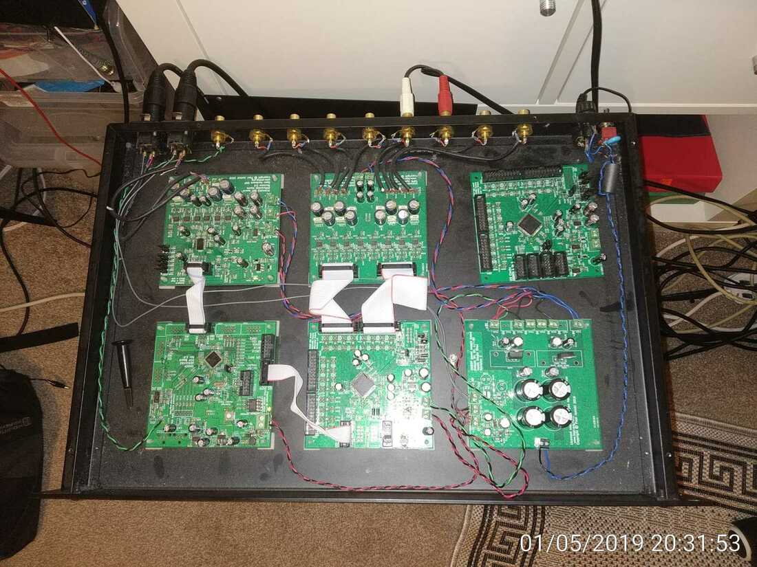
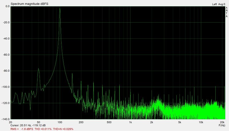
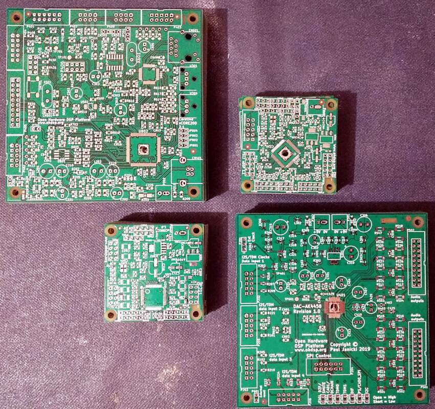
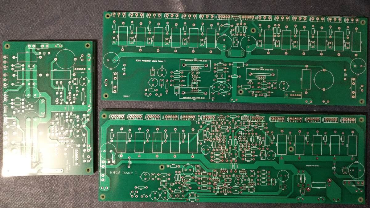
It should be 1.5V with 3.3V analog supply, and 2.25V with 5V. So why do I have 1.5V with 5V supply? The evaluation board manual states that pin 44, used for configuration in standalone mode selects 1.5V (set to 1) or 2.25V (set to 0). However the Rev E datasheet states this should always be set to 0 for standalone mode. Nothing like inconsistent data to help you. I have tried changing this pin with no difference, the investigation will continue... Finally, after quite a break, I have been playing with my 2 input, 8 output box again. Interesting times. ADAU1452 still works as expected with EEPROM writing/booting fine, I left it at this point before moving last year. Running the XLR inputs through ADC, DSP, DAC straight to 2 of the outputs works ok. I have played with it hooked up to my Cyrus One and CM10's. With this in the signal chain, or removed, I could not hear any difference. This was driven from my Asus Xonar U7 USB sound card which is pretty good. Playing a bit more; sometimes on power up, or using the reset button on the DSP board, there is a lot of static/hiss on the outputs. It seems to be coming from the ADC as unplugging the I2S cable removes the noise. Music still sounds fine, so unsure what is the problem. The PCM4202 board has it's own reset circuit, but is not reset from the DSP when this resets. Might trying enabling this with some tacked on wire. Had a quick play with ARTA demo. I am using my Xonar U7 for measurements for now. I am seeing low level 50Hz noise. This is an artefact of my setup. Even with the DSP box switched off (i.e. doing nothing) similar 50Hz is present (maybe 3dB to 5dB lower). On my Cyrus One, which is a sensitive amp (37dB gain), with the volume at max, I could hardly hear any low level hum. I have run some basic THD tests with around 1Vrms on the outputs (max the Xonar U7 line input can take). However these are not accounting for the U7's distortion, although that should be low (not sure at max input level though). 20kHz = 0.046% (THD+N) 10kHz = 0.057% 5kHz = 0.045% 1kHz = 0.031% 500Hz = 0.030% 100Hz = 0.029% I am happy with these for now. There are several issues to resolve, such as why the ADAU1966 reference voltage was low when last measured. All inputs and outputs are single ended, the XLR input negative terminal connects to ground at the Xonar U7 single ended output (which I am lead to believe is the correct way to do it). I also have no idea what I am doing with ARTA as I have not used it before, so this was just a quick play. Oh and I also have a 600Hz and 700Hz test signal on two of the other outputs, generated by the DSP, at around 1.7Vrms. Not sure if crosstalk from these has any affect yet. Example measurement below: New boards arrived, with £5 duty/VAT to pay and a stupid £8 Royal Mail handling charge. Only one minor issue with one set of boards have a routed slot not routed. Also some other boards for some power amps to play with. Might start another site with more of my other hobby stuff on and upload some of these projects to that.
|
Paul JanickiAn electronics engineer and a long term electronics hobbyist. I like tinkering with stuff and making things. Archives
July 2022
Categories |

 RSS Feed
